VMware VXLAN Explained: Advantages and Implementation
Networking requirements continue to grow every year. Modern networks are expected to deliver high speed, low latency, and high scalability. Another common requirement is secure isolation of network segments. Virtualization in datacenters also increases demands on the physical network infrastructure, and traditional networking becomes irrational with potential network issues.
Network virtualization is used to abstract from the underlying physical networks and create scalable and logical networks. It works similarly to virtualization of computing resources (such as processor, memory, and storage), which makes it possible to work with these resources on an abstracted layer.
What is VXLAN?
Virtual Extensible Local Area Network (VXLAN) is an overlay network technology. It is an encapsulation protocol that provides tunneling of layer 2 (L2) connections over an underlying layer 3 (L3) network (below you can find a table with seven OSI layers). The overlay network is a network created on top of any existing network. The underlay network is the physical infrastructure used for an existing network above which the overlay network is built.
The components of the underlay physical network include physical hardware, cables, and network protocols. Border Gateway Protocol (BGP) and Open Shortest Path First (OSPF) are widely used protocols for routing on L3. Common examples of overlay networks are different types of virtual private networks (VPNs), IPSec tunnels, and peer-to-peer networks.
VXLAN specification
VXLAN is defined by the RFC 7348 standard of the Internet Engineering Task Force (IETF). The standardized specification of the VXLAN protocol was developed in collaboration between Cisco, VMware, and Arista, though the standard is not vendor-locked. VXLAN is supported by solutions like VMware’s virtualization software and hardware devices such as routers from various vendors.
Understanding VXLAN
VXLAN allows you to create highly scalable logical networks with the support of multi-tenant broadcast domains and span physical network boundaries. These logical networks are overlay networks. When you decouple the virtual network from a physical network, you simplify the management of large networks, despite the complex initial configuration. When VXLAN is used, you can re-design the overlay network without needing to reconfigure the underlay (physical) network. It is possible to use two or more underlay L3 networks to deploy a virtual overlay L2 network domain. The Leaf-Spine network topology is a good solution for the underlay network to configure VXLAN overlay networks in large datacenters.
Where Can VXLAN Be Used?
The most common use of VXLAN is for creating virtual networks over existing physical and logical network infrastructure when deploying a software-defined datacenter. Abstraction from the underlying physical infrastructure is done for virtualization in software-defined datacenters (SDDC). VXLAN and VMware virtualization solutions allow you to configure a fully virtualized datacenter, in which networks and computing resources are virtualized. The two software products for this purpose are VMware vSphere and VMware NSX. There are two editions of the VMware network virtualization solution: NSX-V and NSX-T.
With VXLAN, virtual machines (VMs) running in VMware vSphere can connect to the needed logical network and communicate with each other even if they are located on different ESXi hosts in different clusters or even in different datacenters. VXLAN logical networks are abstracted from the underlying physical networks, and VMs are abstracted from the underlying hardware.
Without VXLAN, there are higher demands on operating with Media Access Control (MAC) addresses on physical network equipment in datacenters where VMs are running and connected to the network. Many modern datacenters (including datacenters that have virtualization servers) use the leaf-spine network topology and the top-of-rack (ToR) connection scheme. When VMs use a physical network, even with virtual network (VLAN) isolation of network segments on the second layer, the ToR switches (to which rack servers are connected) must operate with MAC addresses of physical network devices and VM network adapters to provide the L2 connectivity (instead of learning one MAC address per link). MAC address tables become too large, which causes switch overload and significantly higher capacity demands of MAC address tables compared to non-virtualized environments. When table overflow happens, a switch cannot learn new MAC addresses, and network issues occur.
Traditional VLAN, spanning tree protocol (STP), and Equal-Cost Multipath (ECMP) cannot perfectly resolve all network issues in a virtualized datacenter. Using overlay networks with VXLAN helps resolve this issue. VM MAC addresses operate only in a virtual overlay network (VXLAN network) and are not sent to physical switches of an underlay network. Moreover, VLANs that are used for network isolation of L2 domains and in multi-tenant environments provide higher limits compared to VLAN. Let’s compare VXLAN vs VLAN to see the main differences between the two.
VXLAN vs VLAN Comparison
The main difference between these network protocols is that VLAN uses a layer 2 underlay network for frame encapsulation while VXLAN uses layer 3 for this purpose. The maximum number of overlay networks is higher for VXLAN.
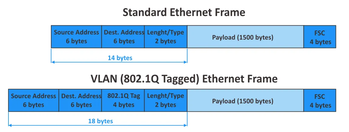
VLAN is documented in the IEEE 802.1Q standard. The maximum number of VLANs supported is 4094 due to the 12-bit segment ID: 2^12=4096, VLAN IDs 0 – 4095, 2 reserved VLAN IDs (0 and 4095 are reserved). These days, 4094 is not enough for large cloud service providers. When using VLAN tagging, the size of an Ethernet frame is increased from 1518 to 1522 bytes. When using VLAN, networks are logically isolated on the L2 by using 802.1Q tags. Configuration of physical network equipment is performed for network segmentation.
VXLAN is an extended analog of VLAN. Some of the main differences between VLAN and VXLAN include:
- The maximum number of virtual networks supported by VXLAN is more than 16 million (2^24= 16,777,216) due to the 24-bit length of the network identifier.
- VXLAN and VLAN use different encapsulation techniques. VXLAN doesn’t require trunking, unlike VLAN, and, STP is not required. It’s not necessary to use VLAN tags when VXLAN network identifiers are used.
- Reconfiguring physical network equipment is not required for a VXLAN configuration.
- Managing large L2 networks becomes difficult in large distributed physical infrastructures. Managing L3 networks is more convenient. VXLAN overlay networks that work over existing L3 networks allow administrators to avoid the usual disadvantages of traditional L2 networks when L2 networks are virtualized by using VXLAN and are not dependent on the physical boundaries of real networks.
Let’s recall the 7-layer OSI model and explore the working principle of VXLAN networks in the next section of this blog post.
The 7-layer Open System Interconnection (OSI) model:
| Layer | Protocol Data Unit | Examples of protocols | |
| 7 | Application | Data | HTTP, FTP, SSH, DNS |
| 6 | Presentation | Data | SSL, IMAP |
| 5 | Session | Data | Various APIs, sockets |
| 4 | Transport | Segment, Datagram | TCP, UDP |
| 3 | Network | Packet | IP, IPSec, ICMP, IGMP |
| 2 | Data link | Frame | Ethernet, PPP, FDDI |
| 1 | Physical | Bits | Wires, Fiber, Wireless |
space
How Does VXLAN Work?
VXLAN encapsulates inner L2 Ethernet frames into L3 IP packets by using UDP datagrams and transmits them over an existing IP network. The VXLAN encapsulation type is known as MAC-in-UDP, which is a more precise term for the technology.
Why is UDP used? Why isn’t encapsulation of VXLAN frames done directly into outer IP packets? L3 networks are convenient for administration, and, as we mentioned earlier, the L3 network is the underlay network for the VXLAN network (which is the overlay network).
The VXLAN header, which is 8 bytes in length, is added to the original Ethernet frame (the inner frame). This VXLAN header is needed to allow a switch on the other side to identify the VXLAN Network Identifier (VNI) to which the frame belongs. Most of us probably would like to package the original frame with the VXLAN header into an IP packet, similar to the Generic Routing Encapsulation (GRE) protocol that is the L3 tunneling protocol.
There is a Protocol field in the IP header (see image below) used to define the data of the higher layer protocol (see the table with the OSI model above) that is packaged into the current IP packet. GRE has protocol number 47, which is defined in the Protocol field of the outer IP packet. VXLAN doesn’t have any associated protocol number, and such packaging directly to an outer IP packet would cause issues. For this reason, VXLAN is packaged by using UDP and, after that, is encapsulated into IP packets. GPRS Tunneling Protocol (GTP) uses a similar approach. The VXLAN UDP port number is 4789. This VXLAN port number should be used as the destination UDP port by default.
You may be thinking: TCP is more reliable. Why is UDP used, not TCP? TCP has a mechanism for checking whether data was received and transmitted successfully without loss. If the data was lost, the data is sent again. UDP doesn’t have these mechanisms. If data is lost due to connection issues, this data is never resent. UDP doesn’t use sessions and timeouts like TCP.
If we would use TCP over TCP, and packets are lost in the underlay session, they are also lost in the overlay session. Packet retransmit is initiated in the underlay and overlay TCP sessions, which causes network performance degradation. The fact that UDP doesn’t initiate a point-to-point (P2P) session is an advantage in the case of VXLAN encapsulation. Note that point-to-multipoint (P2MP) sessions are not available for TCP connections.
VNI or VNID is the VXLAN network identifier. The 24-bit VXLAN network identifier (also called a segment ID) is used, and it defines the maximum supported number of VXLAN networks.
The VXLAN Tunnel Endpoint (VTEP) is an object responsible for encapsulation and decapsulation of L2 frames. VTEP is the analog of a Provider Edge (PE) Router, which is a node for service aggregation. The VTEP can be implemented as a hardware gateway or virtualized solution like VMware NSX (the software VTEP). VXLAN tunnels begin and end on VXLAN Tunnel Endpoints.
VMs connected to the same VXLAN segment can communicate with each other. If host 1 (VM1) is located behind VTEP A and host 2 (VM2) is located behind VTEP B, both hosts (VMs) must have a network interface connected to the same VNI (similar to how hosts must use the same VLAN ID in their network configuration when using VLAN).
VXLAN Frame Encapsulation
Now it’s time to explore the structure of a VXLAN frame encapsulation in detail. In the image below, you see the structure of a VXLAN encapsulated frame. The outer Ethernet header, outer IP header, UDP header, VXLAN header, and inner Ethernet frame used in a VXLAN network are shown.
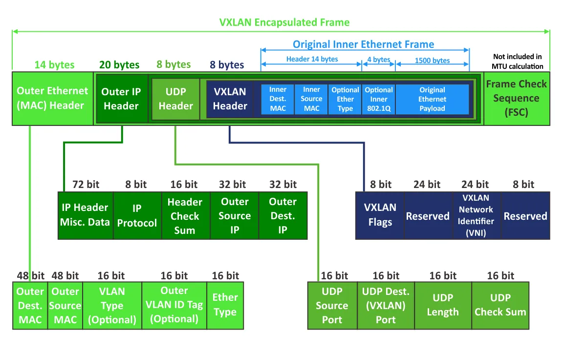
Outer Ethernet (MAC) header
- Outer Destination MAC is the MAC address of a destination VTEP if the VTEP is local to the nearest router, or the MAC address of a router if VTEP is located behind the router.
- Outer source MAC is the MAC address of a source VTEP.
- VLAN Type (optional) is the optional field. 0x8100 points that a frame is VLAN tagged.
- Outer 802.1 VLAN Tag is the optional field to define a VLAN tag (not required for VXLAN networks).
- Ether type defines the type of the packet carried by this frame. 0x800 is referred to IPv4 packet.
Outer IP header
- IP Header misc. data contains version, header length, type of service, and other data.
- IP protocol. This field is used to define an underlying network protocol by which data is carried by the IP packet. 0x11 defines UDP.
- Header check sum is used to ensure data integrity for the IP header only.
- Outer source IP is the IP address of a source VTEP.
- Outer destination IP is the IP address of a target VTEP.
UDP header
- UDP source port is a port set by the VTEP that is transmitting data.
- UDP destination port is the port assigned by VXLAN IANA (4789).
- UDP length is the length of a UDP header plus UDP data.
- UDP checksum should be set to 0x0000 for VXLAN. In this case, the receiving VTEP avoids checksum verification and avoids dropping a frame in case of an incorrect checksum (if a frame is dropped, packaged data is not decapsulated).
VXLAN header
- VXLAN flags are different flags. The I flag is set to 1. The other 7 bits are now reserved and must be set to 0.
- Reserved – reserved fields that are not used yet and are set to 0.
- VNI is the 24-bit field to define the VNI.
- Frame Check Sequence (FCS) is the 4-byte field to detect and control errors.
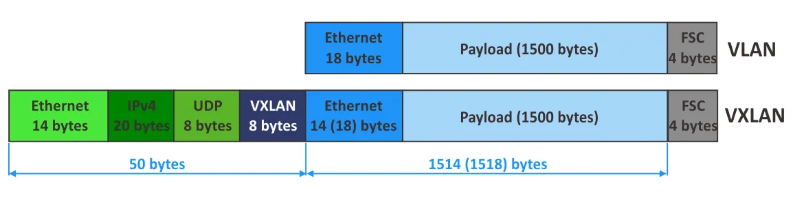
VXLAN Overhead
- Let’s calculate the overhead when using VXLAN:
8 bytes (VXLAN header) + 8 bytes (UDP header) + 20 bytes (IPv4 header) + 14 bytes (outer L2 header) = 50 bytes (if VLAN tagging is not used in the inner frames that are encapsulated). If clients use VLAN tagging, 4 bytes must be added, and the result is 54 bytes.
- Let’s calculate the entire size of outer frames in the physical network:
1514 (inner frame) + 4 (inner VLAN tag) + 50 (VXLAN) + 4 (VXLAN Transport VLAN Tag) = 1572 bytes
- If IPv6 is used, the IP header size is increased by 20 bytes:
1514 (inner frame) + 4 (inner VLAN tag) + 70 (IPv6 VXLAN) + 4 (VXLAN Transport VLAN Tag) = 1592 bytes
- An extra 8 bytes can be optionally added for IPv6. In this case, the outer frame size is 1600 bytes.
- You can change Maximum Transmission Unit (MTU) values in switch configuration accordingly (for example by 50, 54, 70, or 74 bytes). Support of Jumbo frames (frames with a size higher than the standard 1518 bytes) is required in this case.
It is recommended that you increase the frame size when using virtual VXLAN networks in a real network. VMware recommends that you set MTU to 1600 bytes or more on distributed virtual switches.
Note: The Ethernet frame size and MTU are important characteristics of the frame. MTU points to the maximum size of a payload encapsulated into the Ethernet frame (the IP packet size, which has a default value of 1500 bytes when Jumbo frames are not used). The Ethernet frame size consists of the payload size, Ethernet header size, and the FCS.
Example of Data Transferring in VXLAN
Let’s consider an example of transferring data in a network with VMware VXLAN to understand the VXLAN configuration and working principle better.
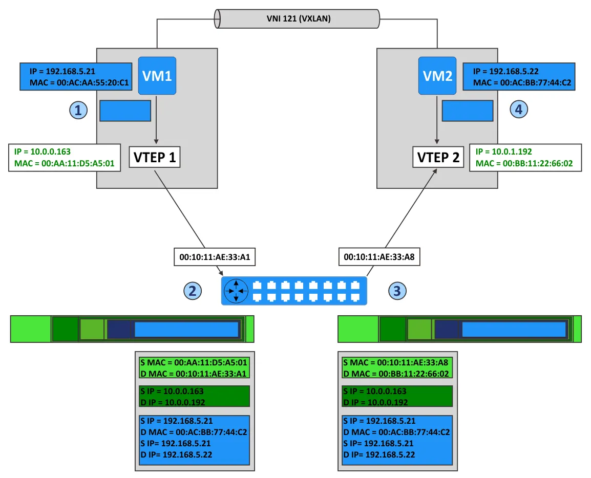
Imagine that we have two ESXi hosts in a VMware vSphere environment with VMware NSX configured. VM1 is running on the first ESXi host, and VM2 is running on the second ESXi host. The virtual network adapters of both VMs are connected to the same VXLAN network with VNI 121. The ESXi hosts are connected to different subnets of the physical network.
Stage 1
VM1 wants to send a packet to VM2. Let’s explore what happens in this situation.
- VM1 sends the ARP packet to request the MAC address of the host with the IP address 192.168.5.22.
- VTEP1, located on the first ESXi host, encapsulates the ARP packet into the multicast packet associated with the virtual network with VNI 121.
- Other VTEPs receiving the multicast packet add the association VTEP1-VM1 to their VXLAN tables.
- VTEP2 receives the packet, decapsulates this packet, and sends a broadcast on port groups of virtual switches that are associated with VNI 121 and the appropriate VXLAN network.
- VM2, located on one of these port groups, receives the ARP packet and sends a reply with its MAC address (MAC address of VM2).
- VTEP2, on the second ESXi host, creates a unicast packet, encapsulates the ARP reply of the VM2 into this packet, and sends the packet by using IP routing back to VTEP1.
- VTEP1 decapsulates the received packet and passes the decapsulated data to VM1.
space
Stage 2
Now VM1 knows the MAC address of VM2 and can send packets to VM2, as displayed in the scheme above for VM-to-VM communication.
- VM1 sends the IP packet from its IP address (192.168.5.21) to the IP address of VM2 (192.168.5.22).
- VTEP1 encapsulates this packet and adds the headers:
- A VXLAN header with VNI=121
- A standard UDP header with the VXLAN port (UDP 4789)
- A standard IP header that contains the destination IP address of VTEP and the 0x011 value to define the UDP protocol used for encapsulation
- A standard MAC header with the MAC address of the next L2 device (the next hop). In this example, this is the router interface that has the MAC address 00:10:11:AE:33:A1. Routing is performed by this router to transfer packets from VTEP1 to VTEP2.
- VTEP2 receives the packet because the MAC address of VTEP2 is defined as the destination address.
- VTEP2 decapsulates the packet and detects that there is VXLAN data (VTEP2 identifies the UDP port 4789 and then identifies the carried VXLAN headers).
- VTEP verifies that VM2 as the target is allowed to receive frames from VNI 121 and is connected to the correct port group.
- After decapsulation, the inner IP packet is transmitted to the virtual NIC of VM2 connected to the port group with VNI 121.
- VM2 receives the inner packet and handles this packet as any usual IP packet.
- Packets are transferred from VM2 to VM1 in the same way.
Multicast Support
VXLAN overlay networks support unicast, broadcast, and multicast communication modes in the network.
- Unicast communication is used to transfer data between two hosts in the network. Remote VTEPs are usually defined statically.
- Broadcast communication is the mode in which one host sends data to all hosts in the network.
- Multicast communication is another one-to-many communication type. Data is sent to selected hosts in the network, not to all hosts. A common example of using multicast is online video streaming. Internet Group Management Protocol (IGMP) is used for multicast communication. IGMP snooping on L2 switches and IGMP Querier on routers (L3) must be enabled.
Note that the ability to use VXLAN for multicast traffic results from the MAC-in-UDP encapsulation method (explained above), which allows establishing P2MP connections. In multicast mode, remote VTEPs can be found automatically without the need to manually define all neighbors. You can define a multicast group associated with a VNI, then VTEP starts to listen to this group. The behavior of other VTEPs is similar, and they start to listen to the group if VNIs are set correctly.
VMware VXLAN Components
VMware vSphere, with ESXi hosts, vCenter, and NSX, is the software suite needed to configure network virtualization with the support of VXLAN. Let’s explain VMware VXLAN components and their role in deploying VXLAN networks.
NSX-V is a solution to build virtual networks in a datacenter with VMware vSphere.
In VMware vSphere with VMware NSX-V, distributed virtual switches (distributed vSwitches or DVS) are used with VXLAN for network abstraction. Using a standard vSwitch is not recommended.
VXLAN encapsulation is performed between a VM’s virtual interface controller (NIC) and the logical port of a distributed vSwitch, which provides transparency for the underlying L3 network and VMs.
NSX Edge services gateway appliance acts as a gateway between VXLAN hosts (VMs) and non-VXLAN hosts. Examples of non-VXLAN hosts are an internet router, a physical server connected to a physical network, etc. The edge gateway can translate VXLAN IDs of VXLAN network segments to allow non-VXLAN hosts to communicate with hosts or VMs in VXLAN networks.
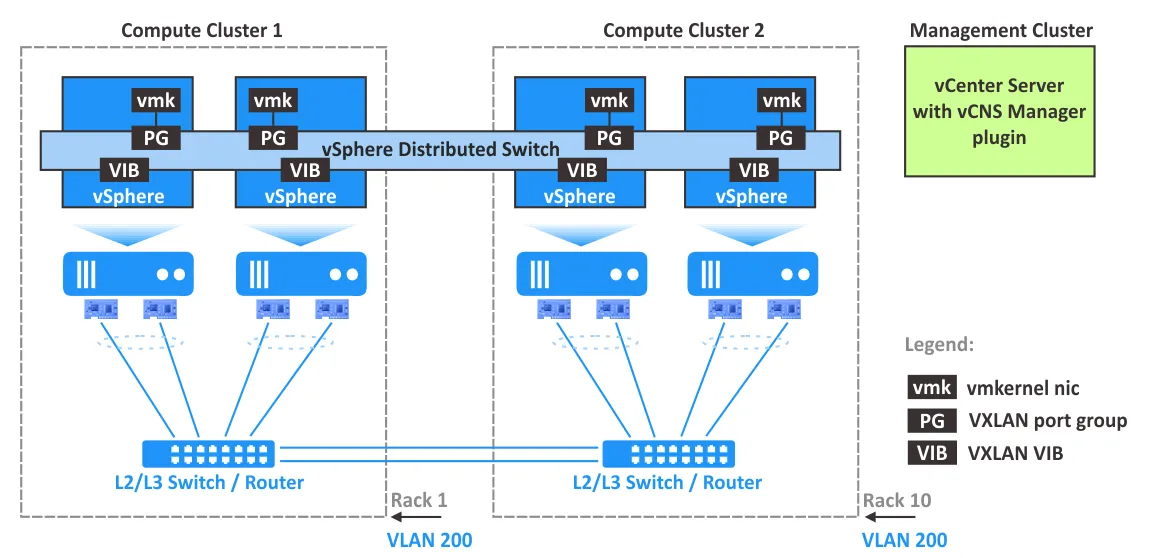
NSX Manager must be installed on an ESXi host managed by vCenter in the vSphere environment. NSX Manager is a virtual appliance used to configure and manage VMware NSX components including controllers, edge services gateways, and logical switches. NSX Manager provides a graphical user interface (a web interface) for a better user experience. After installing NSX Manager, a plugin is injected into VMware vSphere Client. It is recommended that you deploy NSX Manager in a cluster with HA and DRS features enabled. One instance of NSX Manager is used to serve a single vCenter environment.
NSX Controller, called a central control plane, is a distributed state management system to control overlay transport tunnels and virtual networks, providing routing and logical switching capabilities. NSX Controller is required to configure VXLAN networks and must be deployed as a cluster of highly available virtual appliances.
VXLAN VIB packages must be installed on ESXi hosts to support VXLAN capabilities including VTEP functionality.
vmknic virtual adapter carries control traffic, responses to DHCP requests, ARP requests, and multicast join requests. The unique IP address is used for VTEP on each ESXi host to carry VXLAN traffic in created host-to-host tunnels.
VXLAN port groups on virtual switches are configured to define how input and output VXLAN traffic is transferred through VTEP and physical network adapters of ESXi hosts.
VTEP configuration on each ESXi host is managed in vCloud Networking and Security Manager, which is a central place for managing virtualized networks.
It is recommended that you plan the NIC teaming policy, failover settings, and load balancing on a distributed virtual switch in VMware vSphere when you deploy VMware NSX with VMware VXLAN support.
Summary of VXLAN Advantages and Disadvantages
With the working principles of VXLAN configuration and VMware VXLAN implementation covered, let’s look at the advantages and disadvantages of VXLAN.
VXLAN advantages:
- Highly scalable networks: a high number of L2 domains that can be stretched between multiple datacenters.
- Support of multicast, multi-tenancy, and network segmentation.
- Flexibility: STP is not needed. L3 networks are used as the underlying network.
- No overload of physical networks on the second layer. Avoiding MAC table overflow on physical switches when connecting VMs to the networks.
- Centralized network management. Convenient management after deployment and configuration.
VXLAN disadvantages:
- Deployment and initial VXLAN configuration is complicated.
- It may be difficult to scale a centralized controller used for managing overlay networks.
- There is an overhead for headers due to encapsulation techniques.
- The underlay network must support multicast for broadcast, unknown-unicast, and multicast (BUM) traffic.
Conclusion
VXLAN is a network encapsulation protocol that is adopted for virtualization environments where a high number of VMs must be connected to a network. VXLAN allows you to build a virtual L2 network over an existing L3 physical network by using the MAC-in-UDP encapsulation technique. VXLAN network virtualization is the next step after the virtualization of computing resources to deploy a software-defined datacenter. VMware NSX VXLAN support for VMware network virtualization coupled with VMware vSphere is the right solution for this purpose. This combination is widely used by cloud service providers, especially in large datacenters.
If you use VMware vSphere VMs in your server room or datacenter, opt for comprehensive VMware ESX backup solutions like NAKIVO Backup & Replication. NAKIVO’s solution offers powerful features, including incremental, app-aware backups.
NAKIVO Backup & Replication can be installed in multi-tenant mode to offer backup as a service and disaster recovery as a service. MSP clients can then back up their data securely without impacting other clients.
Download the Free Edition of NAKIVO Backup & Replication and try the solution!