MSP Network Topology for Beginners
For managed service providers (MSPs), building a high performance and scalable network is a cornerstone success. In a previous blog post, we covered the basic network topology types, and in this post, we examine more complex network topology types for service providers, including those favored for MSP networks. Read this blog post to learn which topology is the best network topology for an MSP data center, and why.
Traditional 3-Tier Hierarchical Networks
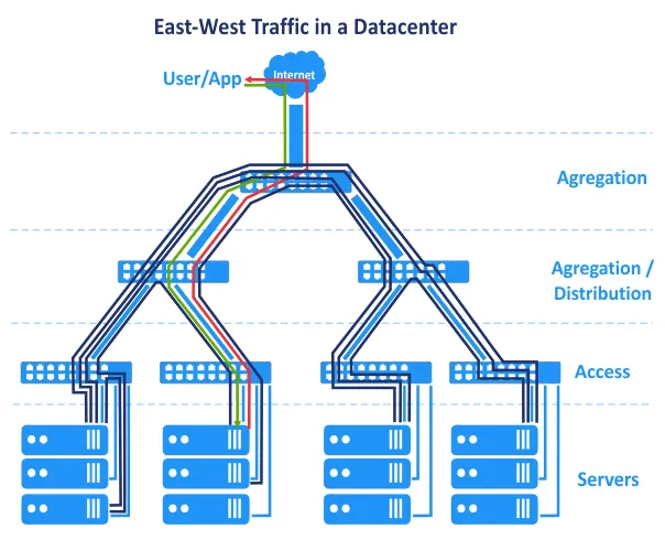
Before Software Defined Networks became common, networks in data centers were based on the hierarchical tree network topology. This topology breaks down into three primary layers: the core layer, the aggregation or distribution layer, and the access layer. In this topology, servers are connected to switches in the access layer. Edge routers are connected to the core to provide access from/to WAN (wide area network) and the internet. These routers are located between the core and the internet on the scheme below.
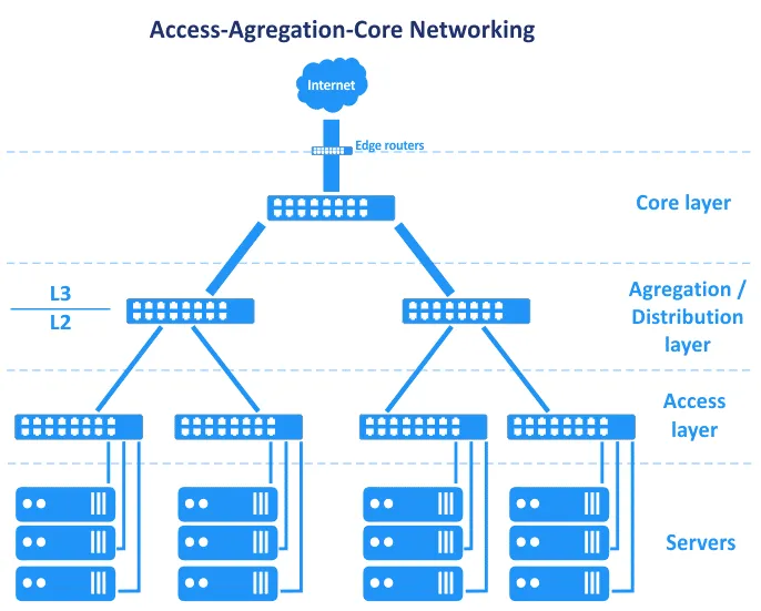
In terms of the OSI (Open Systems Interconnection) model, which divides the network into a data link layer (L2) and network layer(L3), among others, the Access-Aggregation-Core network topology straddles layers, as seen in the graphic.
Let’s look at these three layers in turn.
Core layer
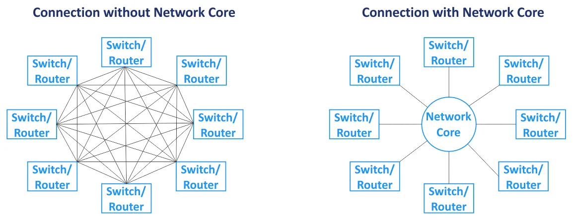
The network core (also called the core network) is the central component of the network as a whole. Primary nodes are connected to the core. The core network is usually based on the mesh network topology, where all nodes are connected to all the other nodes within the core (for a full-mesh network topology type). Switches and routers in the network core are interconnected with high-speed links (that are also called backbone connections). As routers are used in the network core, the core layer operates with L3 traffic.
Distribution/aggregation layer
This is a middle layer used to aggregate uplinks from the underlying layer of the three-tier network topology (the access layer, which operates on L2) to the network core layer (which usually works on L3) by using higher bandwidth links. The distribution layer combines a high number of low-speed ports with a small number of high-speed trunk ports. Routing begins on the distribution/aggregation layer of this network topology when data is transferred from the access layer. The firewall, load balancing, and other security configurations are set on the aggregation layer. The aggregation/distribution layer is used to reduce and simplify the cabling scheme in the data center for more convenient management. Switches installed on the aggregation layer must support storing more MAC addresses in the MAC address table in their memory. While the access layer operates with L2 traffic, the distribution layer operates with L2 and L3 traffic.
Access layer
This layer consists of switches that work on L2. Servers and workstations are connected to the access layer switches. VLANs (virtual local area network) are usually used to separate L2 broadcast domains to reduce broadcast traffic and increase security.
To avoid bottlenecks, thicker links are used closer to the network core. For example, servers are connected to access switches by using 10-Gbit/s network interfaces, access switches are connected to the aggregation switches by using 10-Gbit/s interfaces, and switches/routers of the aggregation layer are connected to network core switches/routers via 100-Gbit/s links. In this case, link aggregation can be used to increase bandwidth and redundancy. All traffic from servers is transferred to uplinks. There is a set of intelligent network equipment, nicknamed ‘god boxes’, located on top of the hierarchy of this network topology. God boxes are responsible for routing and all other services. The hierarchical network topology allows you to create a modular network.
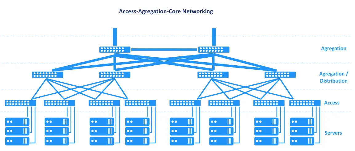
In the network topology seen in the previous diagram, the failure of one link leads to the failure of that segment of the network. For this reason, reserved channels and redundancy are used for this network topology type (see the following scheme) on each network layer. the failure of one device or link causes performance degradation, but the network continues to work. This redundant network topology usually requires STP (Spanning Tree Protocol).
Maintenance. If you disconnect some of the network equipment on top of this 3-tier network topology type to update software or perform other maintenance tasks, network performance degrades. Some services can be temporarily unavailable.
Scalability. The number of services running on servers is growing every year and the amount of traffic is increasing accordingly. This situation requires upgrading and increasing network bandwidth in the MSP network. Increasing network bandwidth in a classic data center usually required the following:
- Increasing link aggregation (LAG) connections
- Buying network cards
- If there are no slots available for installing network cards, buying new servers or related equipment
If you need to add a new server rack (rack cabin) as a new module in your data center, you can increase network bandwidth to this rack and the servers installed in this rack. This type of network topologies cannot ensure a high level of link reservation and redundancy as a result of L2 protocol features such as STP and MSTP (Multiple Spanning Tree Protocol).
The classic three-tier network topology in a data center can be combined with the End of Row and Top of Rack designs. The Top of Rack connection scheme is now more popular. This name is used because servers and switches are connected to the main switch on each rack. The Top of Rack switches (ToR switches) are connected to switches/routers of the higher levels in the MSP network. ToR switches are different from user edge switches, and have multiple extra high-speed uplink ports (such as 10-Gbit/s ports) and a high number of ports to connect servers. ToR switches are installed in pairs for redundancy and to enable switch maintenance. The advantages of this ToR connection scheme are the smaller cable length when cabling devices in a rack and between racks. Access switches of the multi-tier hierarchical network topology are usually used as ToR switches.
Traffic direction
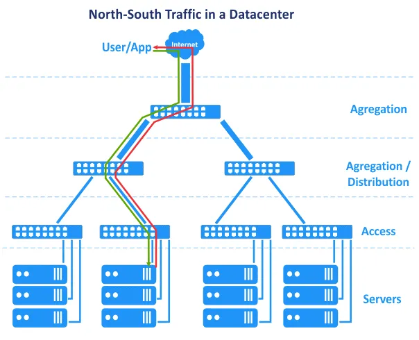
The previously explained disadvantages are not too critical, and a data center network can work successfully with proper administration. Changing L2 to L3 in a part of the network helps resolve a set of issues. There is another feature related to how data centers have evolved and how applications run differently today than they used to. In the 2000s, applications were created using a centralized architecture, and applications of the client-server architecture were primarily monolithic. This means that the components of an application could be located on a single server. As a result, in our diagram, the user request was sent from the top of the network, and the request generated by the application was sent from the bottom server level back to the top of the network. The user request was handled on a single host. Horizontal (east-west) traffic between hosts was minimal, and north-south traffic was in favor. The hierarchical multi-tier traditional network topology used for MSP networks in data centers meets these requirements. However, over time, new architectures were favored when developing applications.
N-tier layered architecture. Application components are distributed across multiple tiers, for example, the logic tier, the presentation tier, and the data tier. Web applications that have multiple components require these components to run on different servers, for example, a web server, application server, and database server. Application components running on multiple servers interact with each other over a network.
Microservice architecture presumes that the components of an application (services) run in separate logically isolated containers that are connected to each other over a network. Containers can run on different hosts in clusters. This architecture is highly scalable and is widely used in clouds nowadays.
In addition, data centers now operate with Big Data, large databases, analytics, context advertising, applications based on artificial intelligence, and other software that requires interconnection with multiple servers, storage arrays, virtual machines, or containers. Application components are distributed across multiple servers or VMs in the data center.
As a result, east-west traffic is higher than the north-south traffic in the MSP network. Internal traffic in a data center network (intra-DC traffic) is higher than the traffic from/to an external user who sends a request to the data center. Don’t forget about internal traffic between storage systems, database replication, data backup, and other service activities using the network in a data center.
On the following diagrams, you can see the graphical representation of growing internal traffic in MSP networks inside data centers over the last few years. The trend shows that intra-DC traffic is growing more than inbound/outbound traffic.
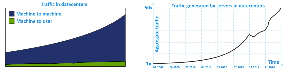
Traditional networks, built using the traditional hierarchical three-tier network topology, are reliable but not adapted for lateral traffic flows in the most rational way. This is due to the emphasis on L2 networking and north-south traffic.
Clos Network Topology
Initially, the Clos network was invented by Edson Erwin in 1938. In 1953, Charles Clos decided to use non-blocking switching networks in telephony systems for more rational usage of communications compared to the crossbar communication scheme. With arrays with a low number of interconnects, inputs, and outputs, the connection scheme seems to be difficult at first glance. However, the Clos network is less complex due to a lower number of connecting points according to the formula: 6n^(3/2)-3n. This fact becomes clear starting from 36 connection endpoints.
If m is the number of input switches and n is the number of output switches, then the blocking characteristics of the Clos network are calculated by using the formula. According to the Clos theorem, a Clos network is strictly nonblocking if the number of second-stage switches m ≥ 2n−1.
The blocking network is a network in which it is impossible to find a communication path from a free input port to a free output port.
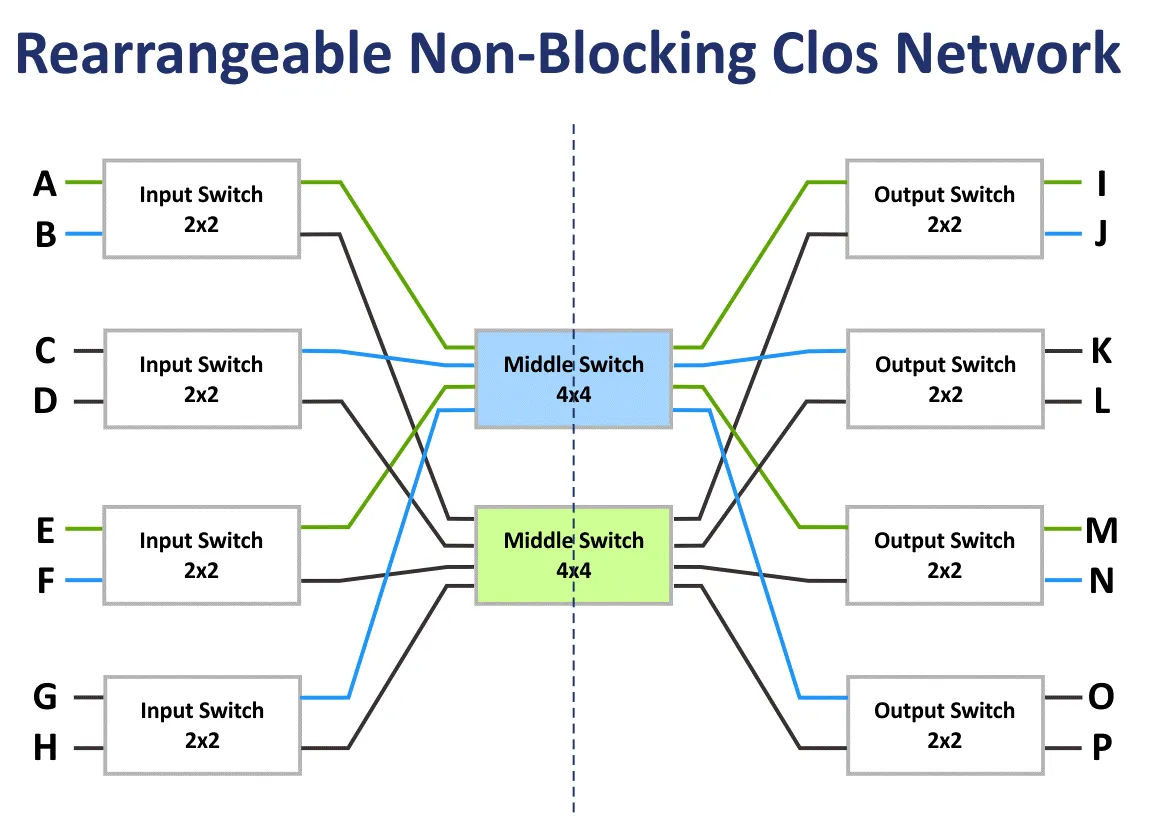
The nonblocking network is the network in which a path to connect any input and output port always exists. Nonblocking networks are created by adding an additional commutation stage.
The rearrangeable non-blocking network is the network in which all possible paths to connect all input and output ports can be re-arranged.
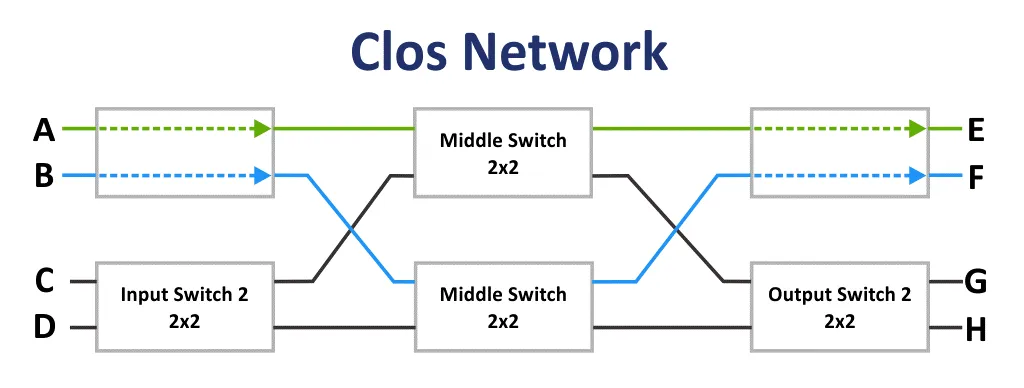
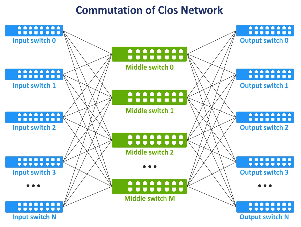
At the end of the 1990s, with the evolution of telecommunication technologies and computer networks, the concept of Clos networks became relevant again. There is a need for all nodes to communicate with each other in the network fabric and, if possible, not to use the full mesh topology when all devices are interconnected. A new communication layer was added for interconnecting network devices. As a result, the Clos network concept was revived in a new incarnation. On the following image, you can see a typical scheme of the tree-layer Clos network.
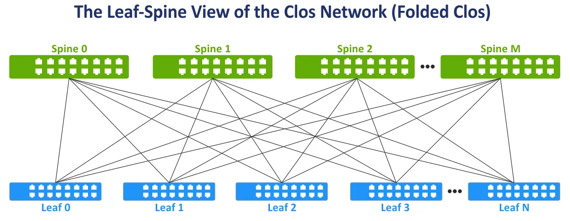
Let’s modify the view of the Clos network to the widely used Leaf-Spine view for more convenience by folding the left and right sides of the scheme. This network topology is known as Leaf-Spine, Folded Clos, and 3-stage Clos network (see the following image).
The spine layer. Spine switches are used to interconnect all leaf switches in the full mesh network topology. The spine layer replaces, to a degree, the aggregation layer used in the traditional three-tier hierarchical network topology. But the spine layer is not a direct equivalent of the aggregation layer. The main task of the spine layer is the fast transfer of data from one leaf to another. Endpoint devices are not connected to spine switches.
The leaf layer. In this model, servers or other endpoint devices in the data center are connected to leaves. All leaves are connected to all spines. As a result, there are a high number of network connections with equal bandwidth between all servers. There are L3 connections between spines and leaves (L3 in the OSI model).
When traffic is transmitted from source to destination in the network, the number of hops is the same (for example, three hops are needed to transfer data between any servers within the two-tier leaf-spine network on the following scheme). The latency is predictable and low. Network capacity is also increased because there is no need to use STP now. When STP is used for redundant connections between switches, only one link can be active at a time.
In the leaf-spine network topology, the Equal-Cost Multipath (ECMP) routing protocol can be used to load balance traffic and prevent network loops (for L3 network connections). BGP, OSPF, EIGRP, ISIS protocols can be used as well.
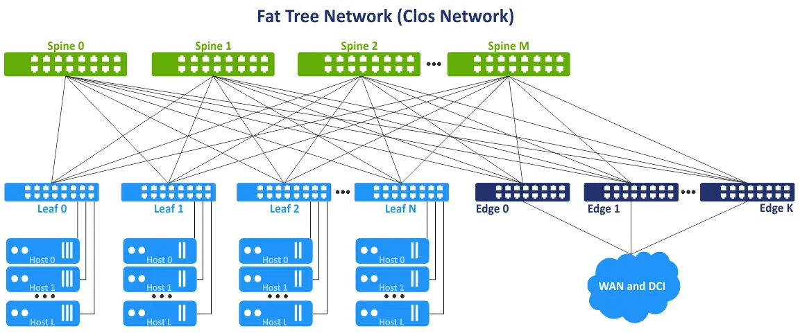
This network concept is also referred to as the multi-layer fat-tree network topology. The idea is to avoid bottlenecks in the upper layers of the tree (close to the root of the tree) and add additional links to increase bandwidth at these segments. As a result, there is a growing link capacity towards the root. The fat tree is a special case of the Clos network. The three-tier Clos network is transformed into a two-tier leaf-spine network after folding. Leaf switches or leaf edge switches/routers can be used to access external networks and other data centers.
Advantages of the leaf-spine network topology
The leaf-spine network topology provides a set of advantages over access-aggregation-core network topology. This set of advantages is the reason to use the leaf-spine network topology type in a data center.
Optimized connections. Links with high bandwidth between network devices are optimal for east-west traffic. There are no unused links (as L3 is used instead of L2). ECMP is recommended for high efficiency, and STP is not necessary.
Reliability. The failure of one device or disconnection of one link doesn’t cause significant negative results and disadvantages. If the ToR switch that acts as a leaf switch is failed, the corresponding rack is affected. If a spine switch fails, the network bandwidth degrades but not significantly compared to the traditional 3-tier hierarchical network topology. Bandwidth degradation for the spine-leaf topology is 1/n, where n is the number of spines. Bandwidth degradation for the hierarchical topology is 50% in this case.
High scalability. You can add new leaves until you have free ports on spines. Adding new spines allows you to increase the uplinks of leaves. Add edge switches/routers to increase bandwidth to external networks. The traditional approach to increase bandwidth and connect more servers for the tree-layer hierarchical network topology is to add more network cards with more ports, network equipment with faster network interfaces, and more powerful hardware in general. This traditional approach is called scale up or vertical scalability.
When using the leaf-spine network topology in data centers and for MSP networks, you can add an additional layer of spines. This approach is called horizontal scalability or scaled out. Adding one typical network device such as a switch/router increases scalability in a linear manner.
Maintenance. You can easily disconnect spines from the network for maintenance or replacement. Maintenance tasks on spine are not risky compared to god boxes because there is no intelligence functionality on spines, and bandwidth reduction is minimal after disconnecting.
Multi-Tier Clos Network
In the previous section, I explained the three-stage Clos network with the stages: Input Switch, Middle Switch, and Output Switch. As devices on the input and output stages are used to receive/send data, the network scheme can be folded by using a middle line consisting of a two-tier leaf-spine network topology. You can add more stages and build the multi-tier Clos network to connect more network devices to this network. In this case, you have five stages: Input Switch, Middle Switch 1, Middle Switch 2, Middle Switch 3, Output Switch.
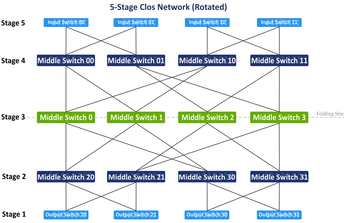
On the following diagram, you can see the initial scheme of the five-stage non-blocking Clos network after the re-arrangement of blue and green blocks. There is also the folded leaf-spine view or the fat-tree (4,3) view (because there are 4 spine switches and 3 stages on the leaf-spine scheme), but let’s let look at how to connect devices into the 5-stage Clos network step by step. A Clos network topology type with more than 5 stages is not common and is not used in practice because the number of connections is too large.
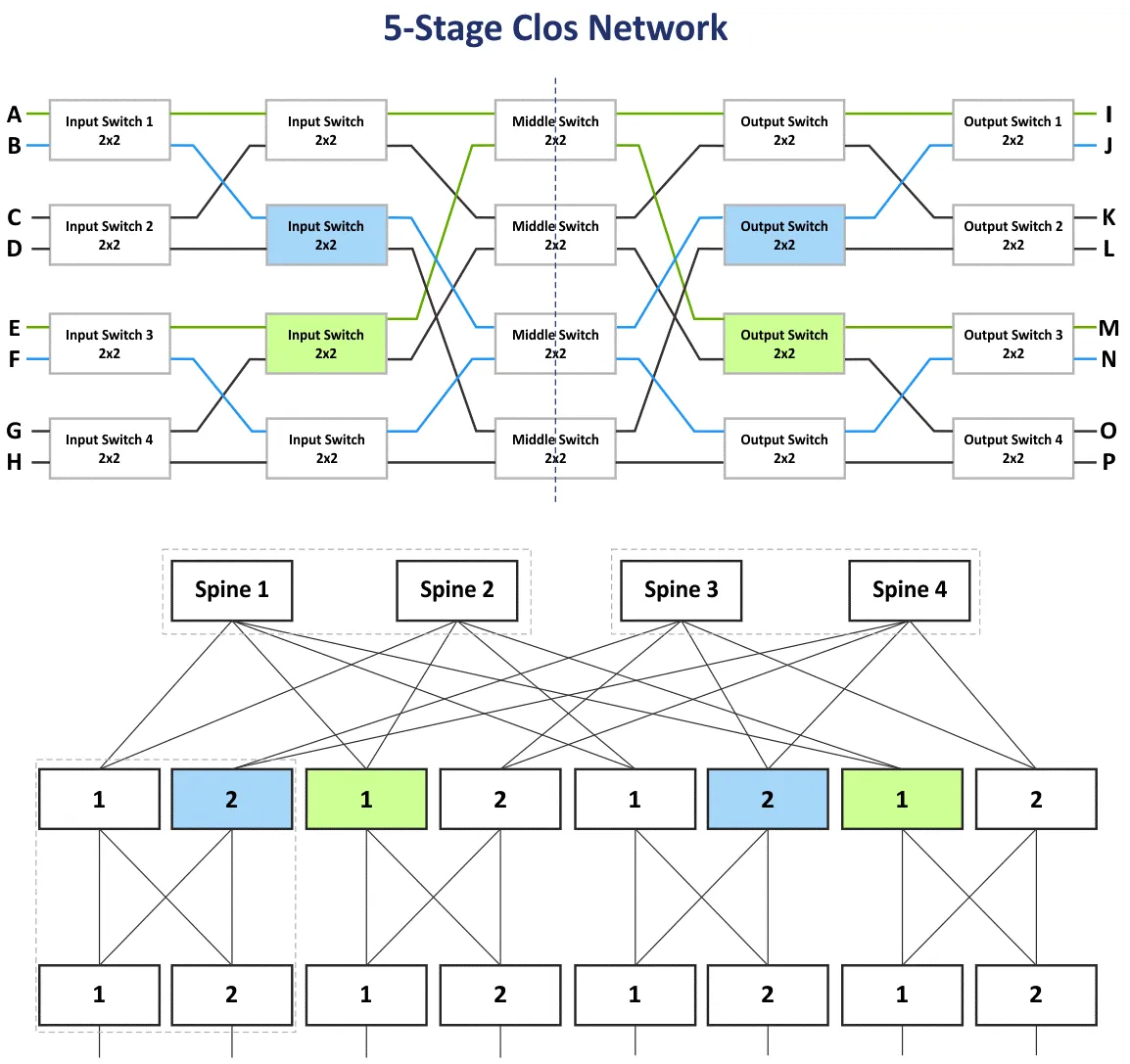
After you rotate the initial scheme of the five-stage Clos network 90 degrees clockwise, you will have the traditional view with input switches, output switches, and three stages of the middle switches. Let’s draw the folding line via the middle switches in the center of the scheme to make the folded view of the five-stage Clos network.
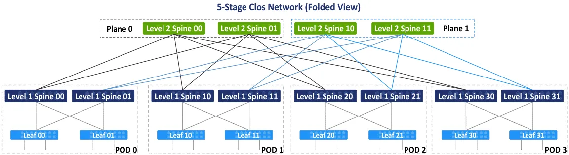
After folding the scheme, you get the folded view or the leaf-spine view of this type of network topologies (see the following scheme). There are 4 individual groups acting as points of delivery (PODs). The POD is the universal unit for building data centers. PODs are connected to the spines of the first level. If you need to extend your data center, or add more servers/network equipment, then add new PODs and connect them to the network fabric. The spines of one POD are connected to the spines of other PODs via second-level spines. At the same time, not all L1 spines are connected to all L2 spines, and they are divided by planes.
There are two planes – Plane 0 and Plane 1 on the following scheme. This concept is used due to the limited number of ports on spines, and creating a fully connected network topology is not possible in this case. In the following scheme, each spine has a limit of 4 ports. According to the main idea, the non-blocking Clos network is based on the same elements (4-port switches, as seen below).
At first glance, you can be confused with terms such as Clos, folded Clos, leaf-spine, and fat tree. Let me clarify these terms.
Clos or Clos network is the term that covers the theoretical basis of the Clos network topology type.
Folded Clos is a more convenient representation of the Clos network, where inputs and outputs have the same role and are located in the same place.
Leaf-spine is a network topology based on the Clos network scheme that is used in practice in data centers to build networks, including MSP networks.
Fat tree is usually referred to as a variation of the Clos network. This term is the most confusing because some articles mention the fat tree as the classic access-aggregation-core network. I refer to the RFC 7938 document that says that the fat tree is based on the folded Clos network topology.
Calculations
You can calculate the number of the core switches, edge switches, total switches needed, and the total number of hosts that can be connected to the network of the selected configuration by using formulas where:
k is the number of ports in the switch
L is the number of levels in the leaf-spine (fat tree) network topology
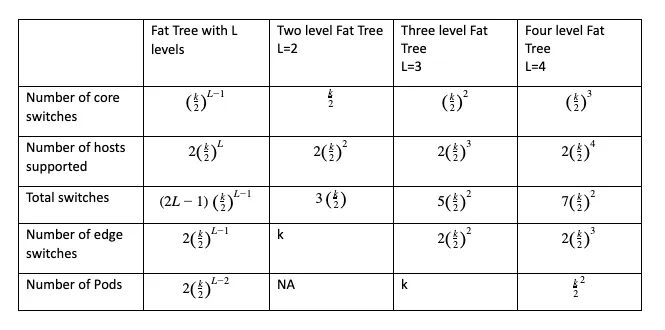
The main parameter to calculate before building your network is the number of supported hosts. The fat-tree configuration can be written as FT(k, L). For example, FT(32,3) is a three-level fat-tree network with 32-port switches. You can use this free calculator for Clos networks that also generates the visualization scheme for the selected configuration.
You can calculate that if your fat-tree network scheme has 2 levels and 8 ports per switch, then you can connect 32 hosts to the network. If you increase the number of ports per switch, the number of supported hosts is increased to 512. As you can see, the number of connected hosts depends on the number of ports on each switch. If you leave the fat tree at 2 levels (the 3-stage Clos network) and increase the number of ports per switch, the number of spines increases significantly. You can resolve this issue by adding one more levels to the fat tree. For a three-level fat tree, if the number of ports per switch is 8, you can connect 128 hosts.
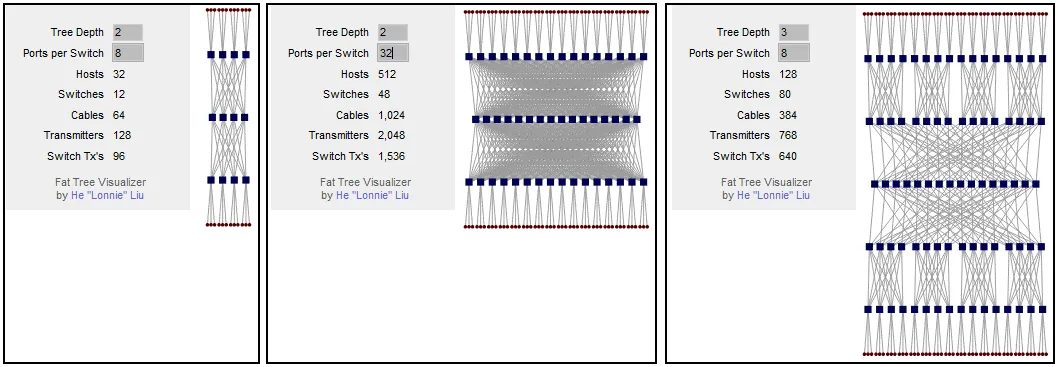
If you increase the number of ports per switch to 32, you can connect 8192 hosts using this network topology. This number for the 5-stage Clos network is 16 times more than that for the 3-stage Clos network. Keep in mind the limitations of the server rack when you plan the installation scheme of servers and network equipment in the data center.
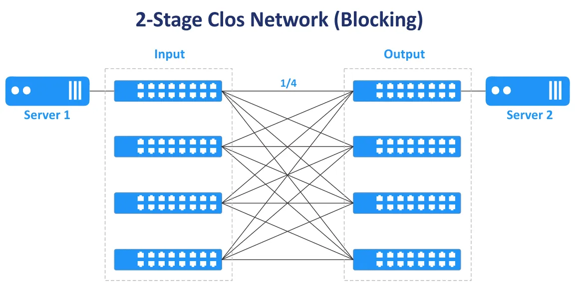
Odd numbers of stages are used to build non-blocking Clos networks (3, 5, 7, etc.). The 2-stage Clos network doesn’t provide nonblocking connectivity and multiple connections between switches.
In the following diagram, you can see that in the case of the two-stage Clos network, there is only one transmission path to connect Server 1 and Server 2. Only ¼ ports are connected, other ports are not connected and they block you.
The over-subscription ratio is the ratio of input bandwidth to output bandwidth in the direction from lower layers to higher layers. The over-subscription ratio usually varies from 2 to 4.
Example: A switch has 48 10-Gbit ports and 4 40-Gbit uplink ports. The total bandwidth of downlinks to servers is 48×10=480 Gbit/s. The total speed of uplinks is 4×40=160 Gbit/s. The oversubscription ratio is 480/160=4.
If the total bandwidth speed is equal for all downlink and uplink ports of the switch, the switch is non-oversubscribed, and there are no bottlenecks in this case. A 1:1 oversubscription ratio is the ideal case. Estimate traffic in different directions before buying switches with the appropriate speed and the number of ports.
Switches that have an oversubscription ratio higher than 1 are often used on the leaf stage in networks of the leaf-spine network topology. Non-oversubscribed switches should be used on the spine stage. Switches on the leaf level in the leaf-spine network topology type are usually used as ToR switches. However, it is possible to install leaf switches as End of Row switches.
Essential differences
When creating a network, some decisions affect the layout of the network. Here are some either-or decisions that affect the functioning of the network.
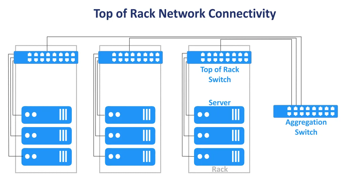
Top of Rack vs End of Row
The Top of Rack (ToR) network connection scheme in a data center is where one or multiple switches are installed in each rack. Short patch cables are used to connect the top of the rack switch with other network equipment and servers within the rack. ToR switches usually have high-speed uplinks to the switches/routers of the higher level and can be connected with fiber-optic cables. The advantage is that when using this connection scheme for a MSP network, you don’t need to install a thick bulk of cables from each rack in the data center. Cable usage in the data center is more rational when using the ToR scheme. In this case, you spend less on cabling and have better cable management. You can manage each rack as a single module without affecting other racks within a data center because servers only in one rack are affected. Despite the scheme name, you can mount a switch in the middle or at the bottom of each rack.
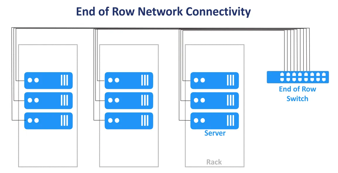
The End of Row (EoR) network connection scheme is when a server rack at the end of the row contains network equipment. The equipment includes a common network switch to connect all servers and other devices of all server racks in the row. Cables from network equipment installed in the EoR server rack are connected to devices in all racks of the row by using patch panels mounted in each rack. As a result, long cables are used to connect all network devices in a row. If redundant network connections are used, the number of cables also increases. Thick bulks of cables can block air access to the equipment.
Server racks are usually located as side-by-side rows in a data center. One row can contain 10 or 12 racks, for example. The whole row is considered a single management unit when using the EoR connection scheme for the MSP network in a data center. The per-row management model is used in this case. Fewer individual switches are needed in the EoR network connection model. Flexibility is lower when you need to perform maintenance or upgrade switches because more devices are affected when an EoR switch is disconnected. Despite its name, a rack with a common switch (switches) can be placed in the middle of the row.
Layer 2 vs Layer 3 Connection
Deciding on the connections within a network is a calculus involving reliability, speed, and expense, as well as the topology being created.
For example, there are network segments for the three-tier Access-Aggregation-Core network topology and Leaf-Spine topology. There, traffic is transferred on the OSI model L2 and L3. In the hierarchical three-tier network, the access layer operates on L2, the distribution/aggregation layer aggregates L2 links and provides L3 routing, the core network layer performs routing on the third layer of the OSI model. The network of the multi-tier Leaf-Spine topology can be configured by using L2 with VLANs and L3 with IP routing and subnets.
L2 network equipment is more affordable than L3 network equipment, but there are some disadvantages when using L2 networking to connect network devices in the MSP network of a data center. VLAN is usually used to logically isolate networks using the same physical environment. The maximum number of VLANs is 4095 (minus some reserved VLANs such as 0, 4095, 1002-1005).
Another disadvantage, as previously mentioned, is the inability to use redundant links when STP is used on L2. This because only one link can be active at the same time, and all the available bandwidth of all links is not utilized. Then the L2 domain with STP becomes large, the probability of issues caused by improper cabling and human error increases, and troubleshooting becomes difficult.
An L3 network configuration allows engineers to improve the stability and scalability of the MSP network and data center networks in general.
The following network protocols help you manage the L3 network and route traffic.
BGP (Border Gateway Protocol) is a protocol for dynamic routing that is widely used and is considered the standard in many organizations with large scale data centers. BGP is a highly scalable, extendable, and efficient protocol.
ECMP (Equal Cost Multipath Routing) is a network routing technology used to distribute traffic by using multiple best paths that are defined by metrics on the third layer of the OSI model. ECMP with routing protocols is used for load balancing in large networks. Most routing protocols, including BGP, EIGRP, IS-IS, OSPF, support ECMP technology.
Always try to use the more progressive network protocols. But remember that the fewer protocols used in the network, the more convenient network administration is.
Network Topology for NV and SDN
In addition to hardware virtualization and using virtual machines, network virtualization with an application-centric approach has also become popular. Network Virtualization (NV) solutions such as VMware NSX, OpenStack networking, and Cisco ASI intensively use east-west traffic in the physical network, and a leaf-spine network topology is suitable for network virtualization solutions for this reason. Read the blog post about VMware NSX to learn more about network virtualization.
Software-defined networking (SDN) is used to virtualize networks for effective resource usage, flexibility, and centralized administration. This is an optimal solution in a virtualized data center where virtual machines connected to the network are used. Virtual machines can migrate between servers, thus creating east-west traffic within the data center. SDN is widely used for MSP networks by MSPs who provide IaaS (infrastructure as a service).
Configuring software-defined networks is effective when using the underlying leaf-spine network topology with dynamic routing, a fixed number of hops, low predictable latency, and east-west traffic optimization for server-to-server communication in a data center.
VXLAN
VXLAN (Virtual eXtensible Local Area Network) is an improved network protocol used instead of VLAN in overlay networks. L2 tunnels are created by using the underlying L3 networks (L3 network underlay) to provide L2 network connectivity without traditional VLAN limitations. With VXLAN, you can configure the L2 network over the L3 network. The virtual topology might be different from the physical network topology of the underlying network.
VXLAN frames are encapsulated into IP packets by using the MAC-in-UDP encapsulation scheme. VNI is the equivalent of VLAN ID. The maximum number of VNI is 2^24, that is, about 16 million. VXLAN is used to create L2 networks in geographically stretched environments, for example, when you need to create a network across two geographically distributed data centers.
Using VXLAN and network virtualization helps optimize the size of the MAC address table for ToR switches. This is because MAC addresses used by VMs and related L2 traffic are transferred via L2 overlay network by using VXLAN. They do not overload the MAC tables of physical switches. MAC address tables of physical switches do not exceed the maximum available table capacity of the switches.
Conclusion
Traditionally, networks in data centers were built by using the classic three-tier access-aggregation-core topology. Given evolving modern client-server and distributed applications, microservices, and other software that are sources of east-west traffic inside MSP networks, the leaf-spine network topology, based on the Clos network concept, is preferred in modern data centers and is one of the more common network topologies. The leaf-spine network topology is the best network topology for large data centers because this topology is highly reliable and scalable. Before installing a network in a data center, make the calculations, and estimate the generated traffic and workloads. Account for service traffic such as backup and replication traffic in the network.
NAKIVO Backup & Replication is powerful virtual machine backup software that can protect VMware Cloud Director workloads, VMware VMs, Hyper-V VMs, as well as physical Linux and Windows machines, Oracle databases. Managed service providers who provide infrastructure as a service (IaaS), backup as a service (BaaS), and disaster recovery as a service (DRaaS) can use NAKIVO Backup & Replication installed in the multi-tenant mode. Download the Free Trial of NAKIVO Backup & Replication for MSPs that supports the multi-tenancy installation mode.